Overview
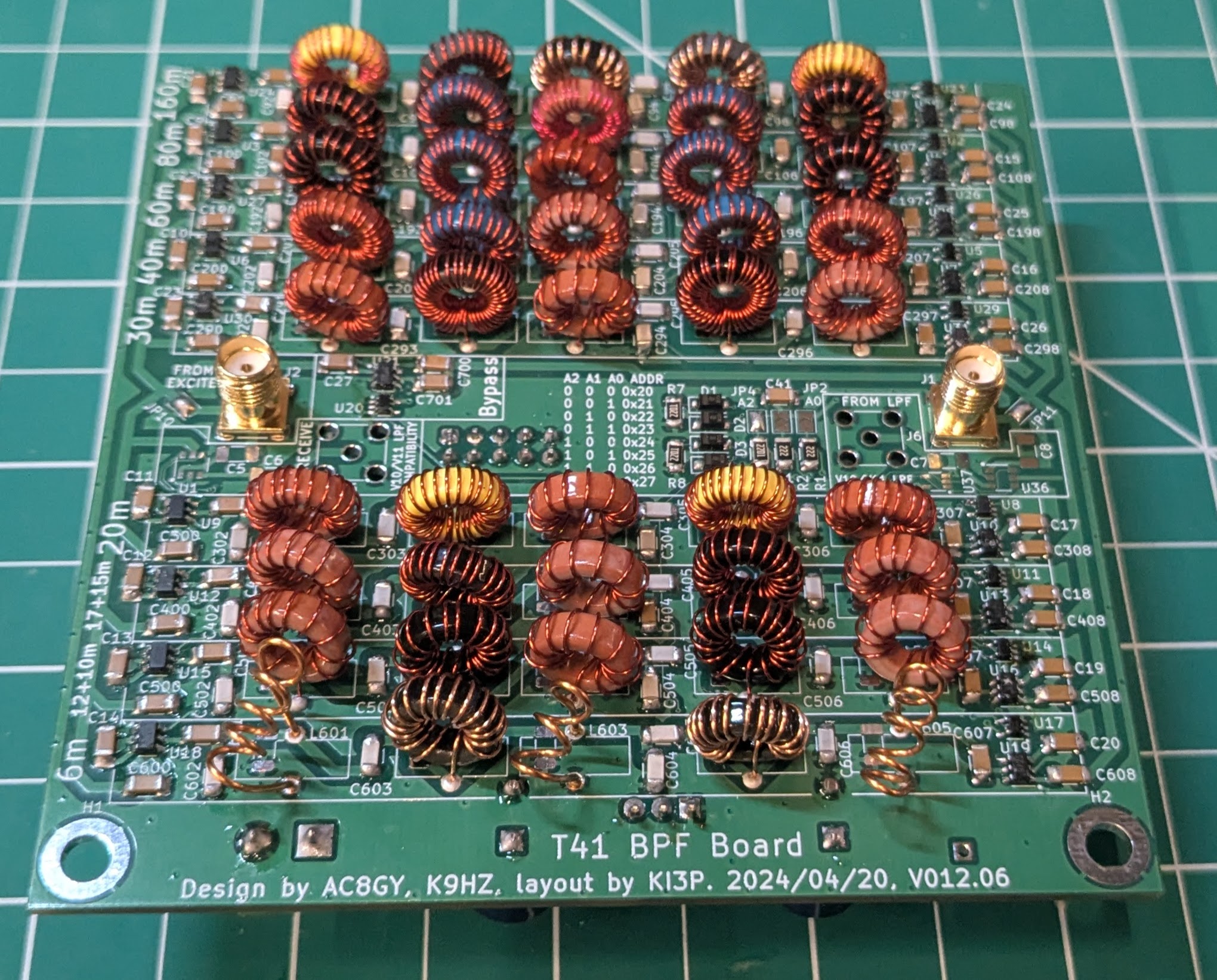
The T41 V12 radio has a bandpass filter board with 9 different filter channels. Each channel has 5 inductors that need to be wound around a toroidal core to achieve the desired inductance. I carefully measured the inductance of each component and tweaked them by hand to get the nicest looking passband I could.
Table
The table below shows the number of windings N on each core for each inductor, the inductance I measured (see methods below), and the desired inductance from the Elsie model.
| Band | Inductors | Core | N | L measured | L goal |
|---|---|---|---|---|---|
| 6m | L601,L605 | Air | 5 | not measured | 39 nH |
| 6m | L602,L604 | T37-10 | 16 | 730 nH | 720 nH |
| 6m | L603 | Air | 7 | not measured | 24 nH |
| 12&10m | L501,L505 | T37-0 | 12 | 110 nH | 120 nH |
| 12&10m | L502,L504 | T37-10 | 17 | 750 nH | 820 nH |
| 12&10m | L503 | T37-0 | 10 | 85 nH | 82 nH |
| 17&15m | L401,L405 | T37-0 | 14 | 148 nH | 150 nH |
| 17&15m | L402,L404 | T37-10 | 21 | 1140 nH | 1200 nH |
| 17&15m | L403 | T37-0 | 10 | 85 nH | 82 nH |
| 20m | L301,L305 | T37-0 | 17 | 198 nH | 220 nH |
| 20m | L302,L304 | T37-6 | 25 | 1845 nH | 2200 nH |
| 20m | L303 | T37-0 | 12 | 110 nH | 120 nH |
| 30m | L291,L295 | T37-0 | 19 | 236 nH | 245 nH |
| 30m | L292,L294 | T37-10 | 38 | 3639 nH | 3600 nH |
| 30m | L293 | T37-0 | 13 | 127 nH | 132 nH |
| 40m | L201,L205 | T37-0 | 32 | 558 nH | 560 nH |
| 40m | L202,L204 | T37-1 | 22 | 3888 nH | 3900 nH |
| 40m | L203 | T37-0 | 23 | 329 nH | 330 nH |
| 60m | L191,L195 | T37-10 | 17 | 750 nH | 840 nH |
| 60m | L192,L194 | T37-1 | 26 | 4985 nH | 5200 nH |
| 60m | L193 | T37-2 | 9 | 394 nH | 400 nH |
| 80m | L101,L105 | T37-10 | 20 | 1035 nH | 1000 nH |
| 80m | L102,L104 | T37-1 | 27 | 5550 nH | 5600 uH |
| 80m | L103 | T37-0 | 32 | 558 nH | 560 nH |
| 160m | L91,L95 | T37-6 | 26 | 1974 nH | 2000 nH |
| 160m | L92,L94 | FT37-61 | 15 | 10619 nH | 11000 nH |
| 160m | L93 | T37-10 | 20 | 1035 nH | 1000 nH |
Plots
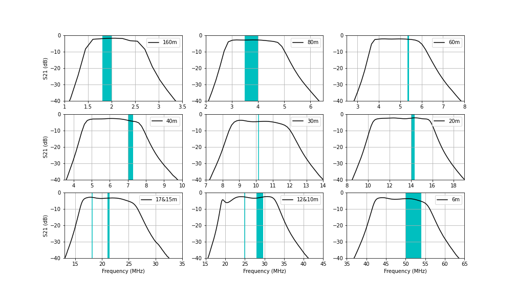
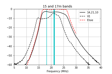
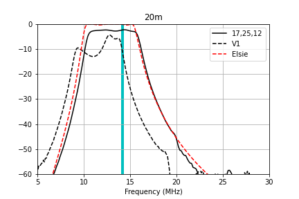
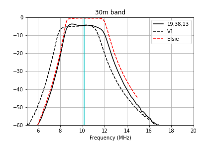
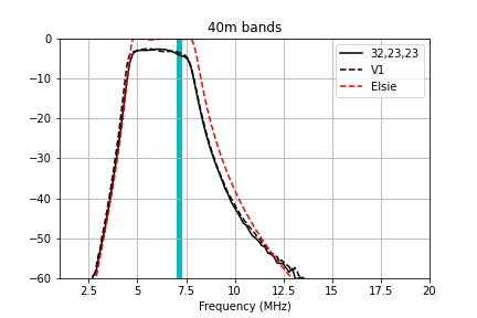
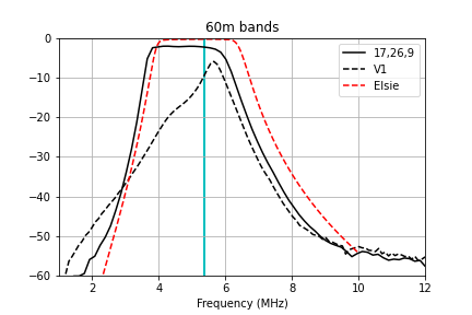
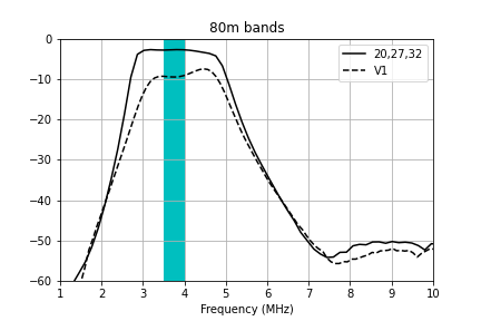
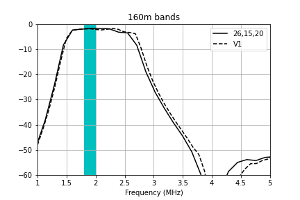
The measured passband for each of the filter channels is plotted below.
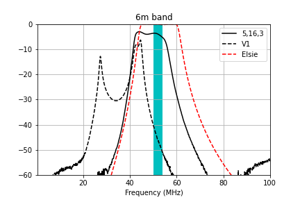
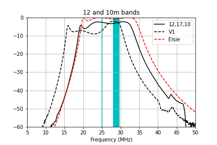
Here are zoomed-in plots that compare the measured transmission to the Elsie simulation and my prior attempt at winding the filters (V1) for each of the bands. The windings specified in the table above give very good performance that matches the Elsie simulations fairly well.
Methods
I measured the inductance of each toroid using one of two methods.
Direct measurement with a VNA
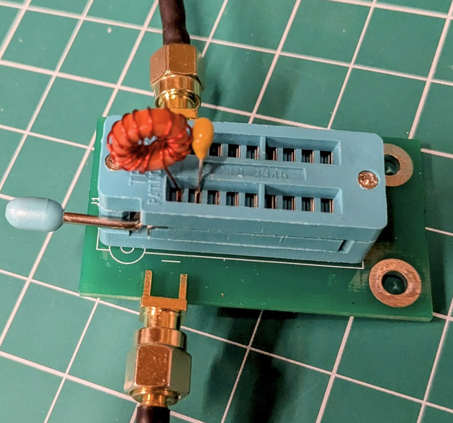
Use a ZIF socket soldered to a PCB to hold the inductor. Using SMA connectors, place the inductor in a series circuit as shown below.
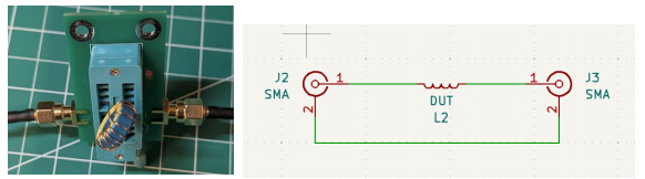
I use the NanoVNA-Saver software and a NanoVNA to measure the inductance of the fixture and device under test (DUT). Note that the VNA must be calibrated. NanoVNA will calculate the equivalent series inductance for you.
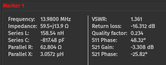
You can also export the measured response as a Touchstone s2p file. I then use Python and the scikit-rf library to calculate the equivalent series inductance from the magnitude of the imaginary part of S[1,1]:
import skrf as rf
def calculate_L_nH(S):
    return (S.s11.z_im.flatten())/(2*rf.pi*S.f)*1e9
S = rf.Network('file.s2p')
L_nH = calculate_L_nH(S)
It looks something like this:
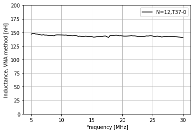
It’s critical to note that this measurement includes the inductance of the test fixture! The fixture inductance needs to be subtracted to obtain the DUT inductance. I measure the test fixture inductance by placing a short conductor between the terminals of the ZIF socket; I measured it to be 30 nH.
It’s also important to note that the ZIF socket has an equivalent series capacitance of roughly 4 pF (again measured using a NanoVNA). The resonance frequency between the ZIF socket capacitance and the inductor under test approaches HF frequencies for high inductance values, which gives false readings using this method. Based on testing, I’ve concluded that measuring inductor values above 2 uH is unreliable using the VNA method and this particular test fixture. For such inductors I use the resonance method.
Resonance method
In this method, place a capacitor in parallel with the inductor under test and measure the frequency of the minimum in the transmitted signal S21.
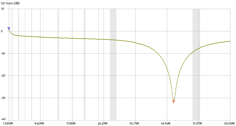
This frequency is the resonance frequency of the tank circuit formed by the inductor under test and the reference capacitor. The exact capacitance of the reference capacitor can be found by measuring the equivalent series capacitance of the capacitor when placed in the ZIF socket using the NanoVNA software. It should be higher than the listed value of the capacitor due to the ZIF socket’s parasitic capacitance.
Once you have the resonance frequency, calculate the inductance using this formula:
\[L_{\rm DUT} = \frac{1}{C_{\rm ref}(2 \pi f_{\rm res} )^2}\]Note that you do not need to subtract the inductance of the test fixture when using this method – its inductance doesn’t become part of the resonating circuit.